1.0 Prerequisites
1.0.1 To follow this guide, ensure you are able to develop and test outside, or near a southern facing window (northern facing if south of the equator) with a clear view of the sky.
1.0.2 Windows and PuTTy are used to communicate with the board in this guide.
1.0.3 From our testing, in order for the device to operate properly, it is strongly recommended that an external GPS antenna is used. Please contact Murata if you do not have access to a GPS antenna."
1.0.4 We work as a wholesale provider and have many connectivity partners. Need a SIM card to get started testing this device? Please contact one of our partners to get started.
2.0 Hardware Getting started
2.1 Out of the box
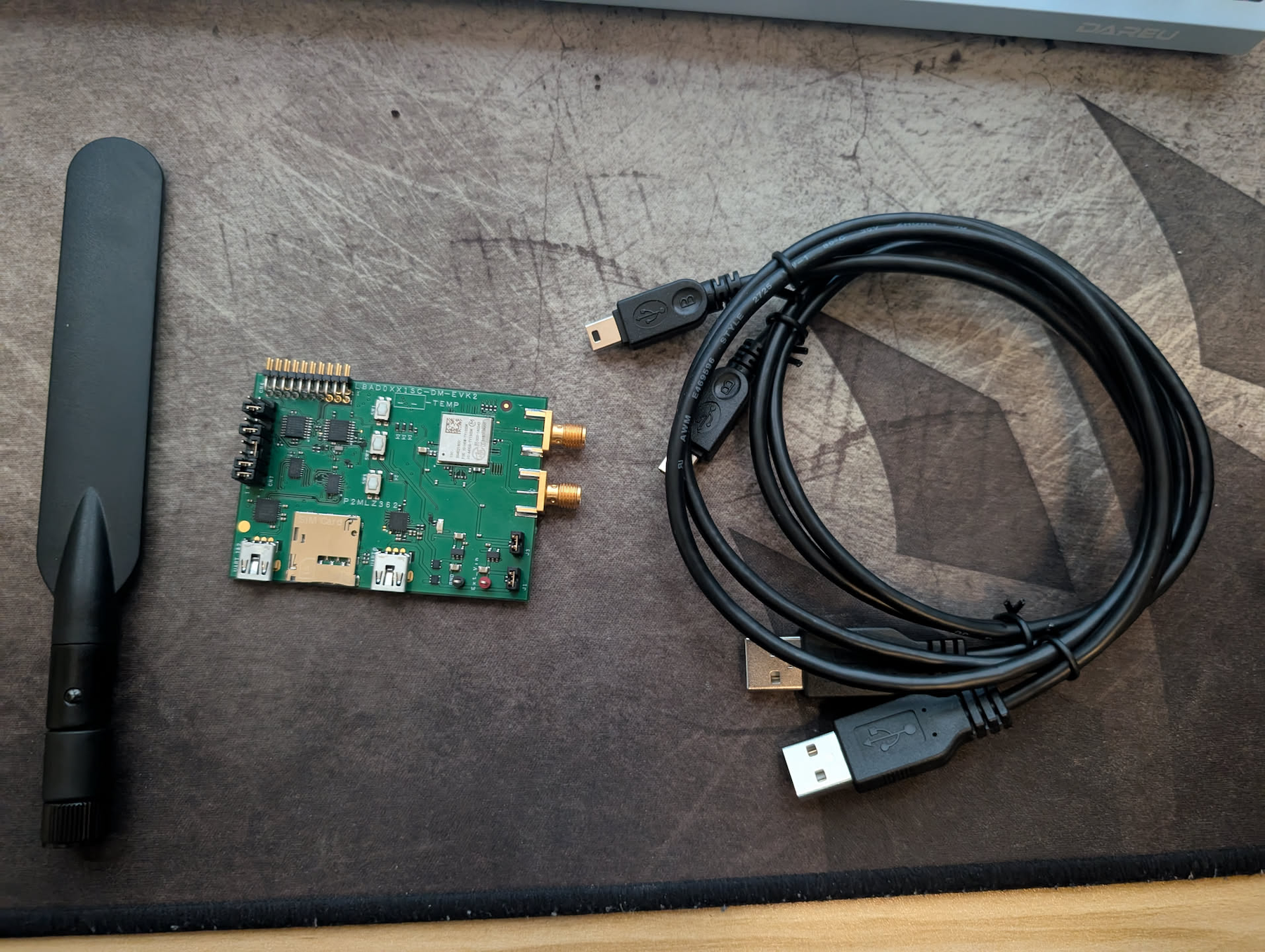
2.1.1 The following items are included in the Murata Type1SC evaluation kit:
- Type1SC board
- 2 Mini USB to USB type A cables
- Antenna
2.1.2 Only a single mini USB is required for development and testing. Plug one of the USB cables into UART0, the right USB port.
2.2 SIM Card
2.2.1 The UMTS & ELT EVB accepts a micro SIM card. Ensure that the SIM is subscribed to NTN connectivity.
2.2.2 Insert the SIM card with the metal pads facing down.
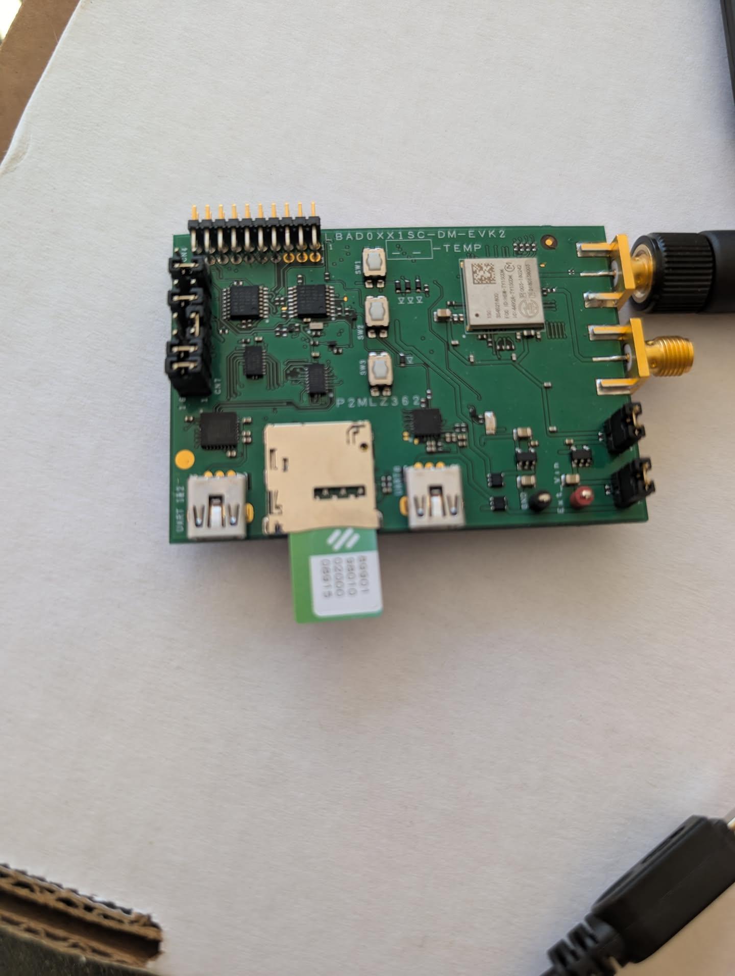
2.2.3 Push the SIM card in until it clicks into place.
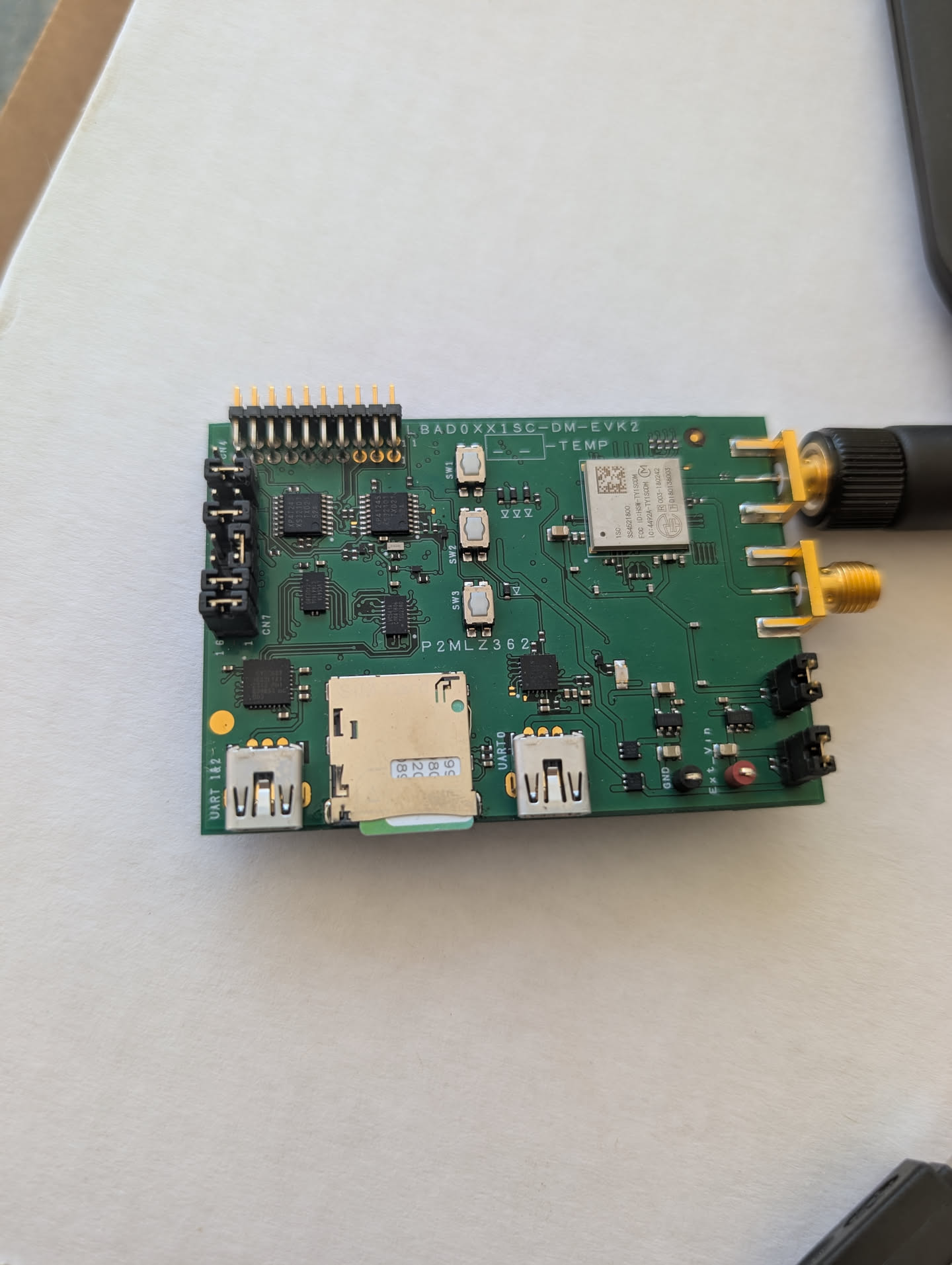
2.3 Power the board
Both USB ports are able to supply power to the board.
2.4 Power on instructions
Once the device is assembled, connect power to the board. Press SW 2 (The middle button) and the board will start up. The LEDs on the board do not stay on to indicate power.
3.0 Software Getting Started
3.1 USB Drivers
3.1.1 Murata recommends installing the drivers from the following page: https://www.silabs.com/products/development-tools/software/usb-to-uart-bridge-vcp-drivers
3.1.2 We recommend using the CP210x VCP Windows driver version.
3.1.3 Extract the ZIP file and run the installer executable for your architecture (x64 if on Intel or AMD systems).
3.1.4 After running the installer, the device now shows up in device manager:
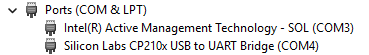
3.1.5 Keep note of the COM port.
4.0 Communication: PuTTy
This is the easiest way to get connected and the most standard.
4.0.1 Install PuTTy: https://www.putty.org/
4.0.2 Once putty in installed, change the connection type to serial, set the baud rate to 115200, and the Serial line to the port listed in task manager:

4.0.3 Change connection type to serial, speed to 115200, and Serial Line to whatever the USB modem or serial cable shows up as in the device manager. Clicking enter will prompt the PuTTY terminal to open. If the terminal opens but you cannot type AT commands into it, then you most likely have the wrong COM port entered. Reverify and try again.This behavior may also be due to the board not being on.
5.0 Connecting to Skylo
Much of the content below is sourced from Skylo partner Monogoto’s excellent AT command guide.
5.0.1 Once you have an open terminal with the board, you can start to configure it using AT commands. Enter the following commands in order.
AT%SETACFG="radiom.config.multi_rat_enable","true"
AT%SETACFG="radiom.config.preferred_rat_list","none"
AT%SETACFG="radiom.config.auto_preference_mode","none"
AT%SETACFG="locsrv.operation.locsrv_enable","true"
AT%SETACFG="locsrv.internal_gnss.auto_restart","enable"
AT%SETACFG="modem_apps.Mode.AutoConnectMode","true"
ATZ
5.0.2 Here we are using the SETACFG command (set a configuration) to configure the board for NTN access.
5.0.3 Restart the board with ATZ to enable the configuration changes
AT%RATACT="NBNTN","1"5.0.4 Switch to NB-IoT NTN Radio Access Technology (RAT). “1” tells the board to write this setting into non volatile memory
AT+CFUN=05.0.5 Disable the radio while we are configuring it
AT%PDNSET=1,"YOUR.APN","IP"5.0.6 Set the APN of the board. Note that the APN to use is defined by your Skylo Partner depending on what SIM card you are using. Contact your provider if you are unsure of what APN value to use.
AT%SETCFG="BAND","255"5.0.7 Set the NTN band. Many countries and regions have different bands depending on regulatory requirements.
- 255: Global L-band. Countries include United States, Taiwan, New Zealand, and Japan
- 23: Canada
- 256: S Band. Most European countries
AT%NTNCFG="POS","IGNSS","0"5.0.8 The board needs its current location to communicate with the satellites. This command sets the position source to its internal GNSS sensor.
ATZ5.0.9 Restart the board to enable configuration changes.
AT+CFUN=05.0.10 Disable the radio.
AT%IGNSSEV="FIX",1
AT%NOTIFYEV="SIB31",1
5.0.11 Enable notifications. This causes the board to send data over the terminal unprompted. We are enabling notifications for GNSS, so we will get position updates.
AT+CEREG=25.0.12 CEREG represents carrier registration. Here, we put it into state 2. State 2 indicates that the board is searching for a network to connect to.
AT%IGNSSACT=15.0.13 Now that the board is fully configured, enable the IGNSS and wait for a location.
Wait for a location - this may take a bit
5.0.14 If after a bit of time no response has been given, you may need to relocate to outside. During development of this article, it took 3 minutes to fix a location.

AT+CFUN=15.0.15 Re enable the radio. At this point, the board is actively searching for a connection. It may take a bit of time for it to connect to the Skylo network.
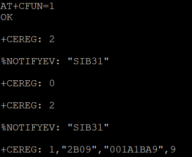
Once CEREG returns a value of 1 or 5, then you are connected to Skylo!
5.0.16 You can validate the quality of your signal with the following command:
AT%PCONI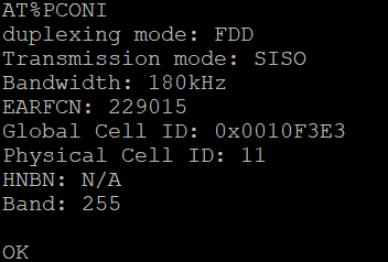
5.1 Troubleshooting
5.1.1 If you are unable to connect, there are a few common issues. Below shows the meaning of the carrier registration codes:
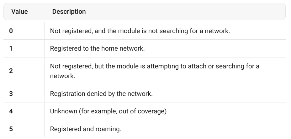
5.1.2 If the board gets stuck on CEREG 0 or 2, it likely cannot find the network. This is most likely due to connectivity issues. Ensure you are outside/have a clear view of the sky. Ensure that you are facing south ( North if south of the equator) and are not obstructed by buildings. Skylo utilizes geostationary satellites that orbit above the equator.
5.1.3 An incorrect APN set would also cause registration to be denied. Ensure that the APN is set correctly to the value provided by your Skylo partner.
5.2 Test the connection
5.2.1 Ping
5.2.1.1 Send a ping to Cloudflare’s DNS server:
AT%PINGCMD=0,"1.1.1.1",1,56,60- 0 tells the board to use IPv4
- “1,1,1,1” is the IP address to ping
- 1 is the number of ping request retries
- 56 is the packet size in bytes. Overall packet size is 64 after factoring the ICMP header
- 60 is the timeout.
5.2.1.2 A response will look similar to this:

5.2.2 Send a packet
5.2.2.1 To test the capability of the Murata Type 1sc, lets try sending and receiving a simple UDP packet over Skylo.
5.2.2.2 Below is a basic Python script that will output the payload of anything it receives in a UDP packet on port 12345.
import socket

UDP_IP = "0.0.0.0"  # Listen on all available interfaces
UDP_PORT = 12345

sock = socket.socket(socket.AF_INET, socket.SOCK_DGRAM)  # UDP

sock.bind((UDP_IP, UDP_PORT))

print(f"Listening for UDP packets on {UDP_IP}:{UDP_PORT}")

while True:
    data, addr = sock.recvfrom(1024)  # buffer size is 1024 bytes
    print(f"Received message from {addr}: {data.decode('utf-8', errors='ignore')}") # decode and print the data. errors='ignore' prevents crashes from non-utf-8 characters.
5.2.2.3 Ensure that this script is running with access to port 12345 over the open internet. Configure firewalls to port forward if you are behind NAT. You can test this with netcat:
echo "Accessability Test" | nc -u 1.2.3.4 123455.2.2.4 Now, to send a packet from the Type 1sc, use the following commands:
AT%SOCKETCMD="ALLOCATE",1,"UDP","OPEN","1.2.3.4",7,123455.2.2.5 Here we allocate a UDP socket to an IPv4 address, replace 1.2.3.4 with the address of your machine.
AT%SOCKETCMD="ACTIVATE",15.2.2.6 Activate the socket connection.
AT%SOCKETDATA="SEND",1,13,"48656c6c6f2066726f6d20537061636521"5.2.2.7 Send a hexadecimal encoded payload over the socket connection
AT%SOCKETCMD="INFO",15.2.2.8 Get information about the connection. Gives source and destination IP addresses
AT%SOCKETCMD="DELETE",15.2.2.9 Close the socket connection and deallocate it.
5.2.2.10 Checking back in on the UDP server

Murata has great documentation on the SOCKETCMD command in their Socket Service Application guide (My Murata account required).
6.0 Simple Proof of Concept Use Cases
The following are some simple applications that can be created to utilize NTN functionality:
- Always connected GPS tracking
- Log the GPS location of a device no matter where on the earth it is located. Use Google Maps Javascript framework and a simple backend to show the live location of the device in real time.
- Always connected sensor monitor
- Record readings from a sensor and upload those values from anywhere on the planet. Import this data into a metric monitor like grafana
- Always connected security sensor
- Setup a sensor to detect movement in remote sites or locations.
7.0 Helpful Links
- https://docs.monogoto.io/ntn-satellite-networks/ntn-certified-devices/ntn-certified-modules/murata-alt1250-satellite-ntn-network
- https://www.murata.com/en-us/products/connectivitymodule/lpwa/overview/lineup/type-1sc
- https://www.murata.com/en-us/products/connectivitymodule/cat-m1/design-development#anchor-1
Author:
Eli Bollinger