
1.0 Prerequisites
1.0.1 To follow this guide, ensure you are able to develop and test outside, or near a southern facing window (northern facing if south of the equator) with a clear view of the sky.
1.0.2 Windows and PuTTy are used to communicate with the board in this guide.
1.0.3 We work as a wholesale provider and have many connectivity partners. Need a SIM card to get started testing this device? Please contact one of our partners to get started.
2.0 Hardware: Getting started
2.1 Out of the box
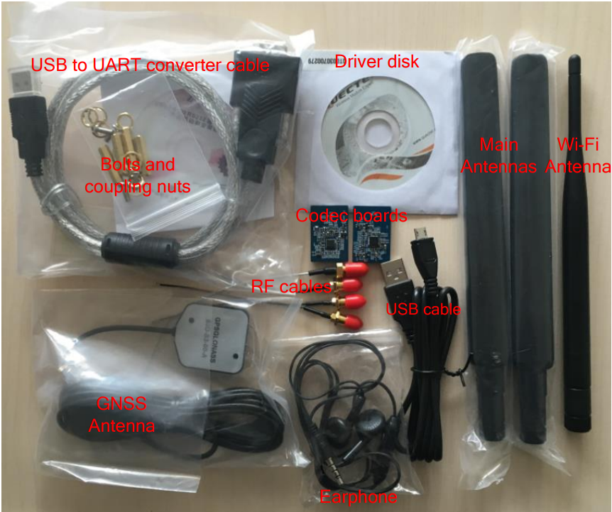
2.1.1 The following items are included in the Quectel UMTS & LTE evaluation kit:
- Serial (UART) to USB converter cable
- Driver disk
- Driver USB stick
- 2x Main antennas
- GNSS antenna
- Wifi antenna
- Earphones
- 4x RF cables
- Micro-USB to USB type A cable
- Realtek ALC5616 Codec board
- Texas Instruments TLV320AIC3104 Codec board
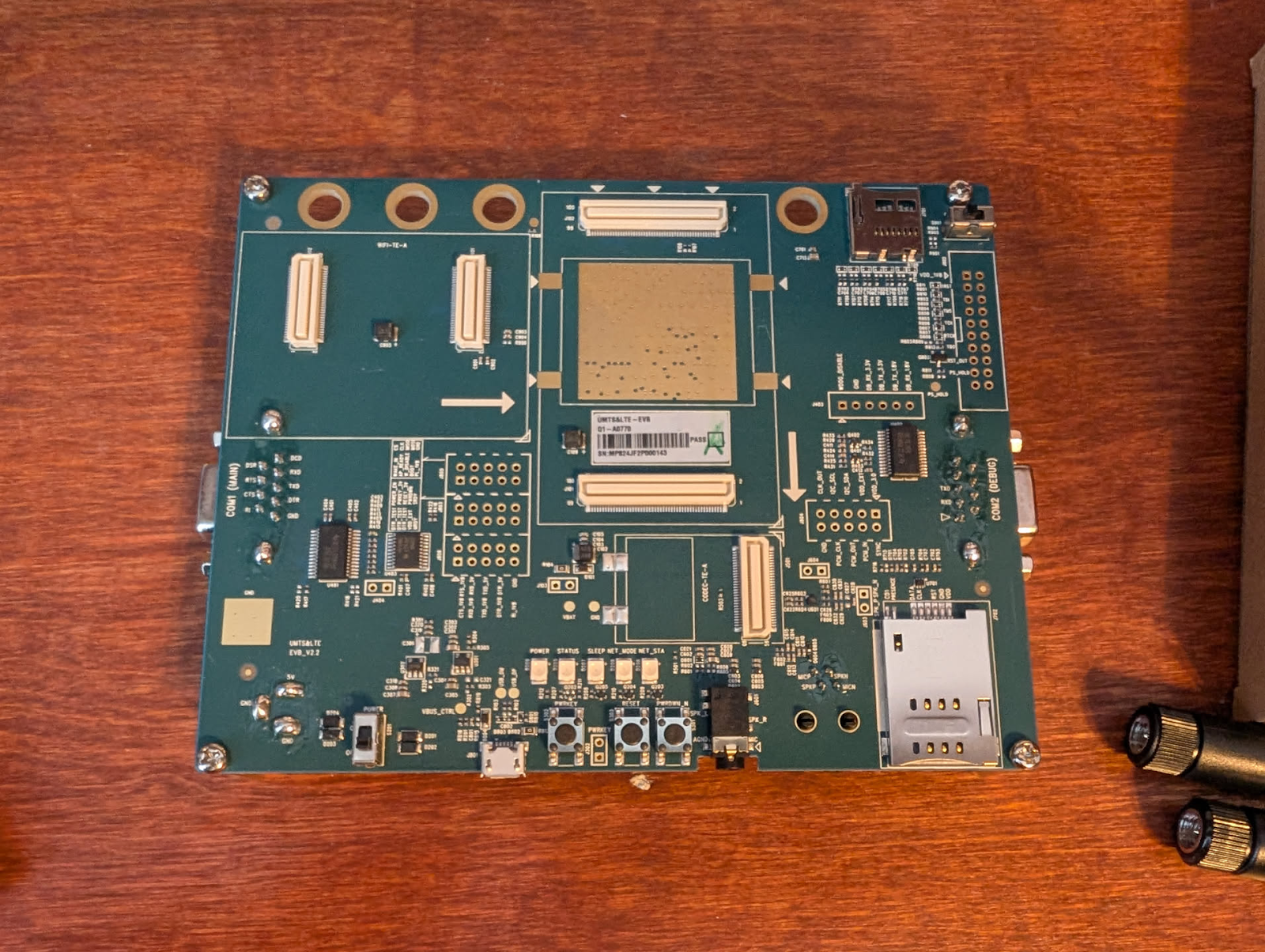
2.2 Assembling the kit
This article focuses only on NB-NTN connections, thus there will be no wifi board, and the wifi antenna and one of the RF cables will be unused.
There are two codec boards included in the box. These are for decoding audio for the 3 audio interfaces on the board. Either codec board will work and is only necessary if voice/calling functionality is required.
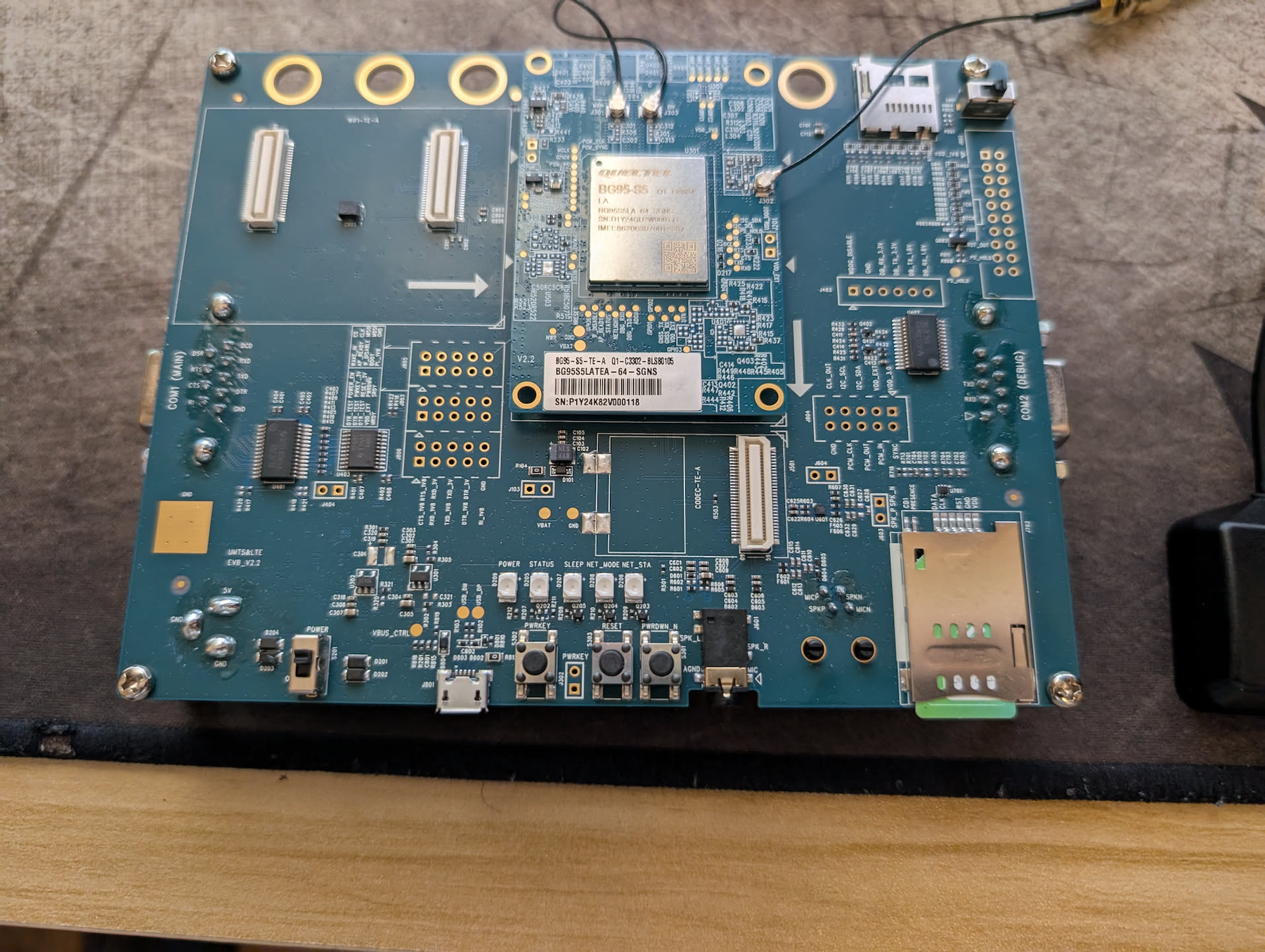
Starting with the base evaluation board:
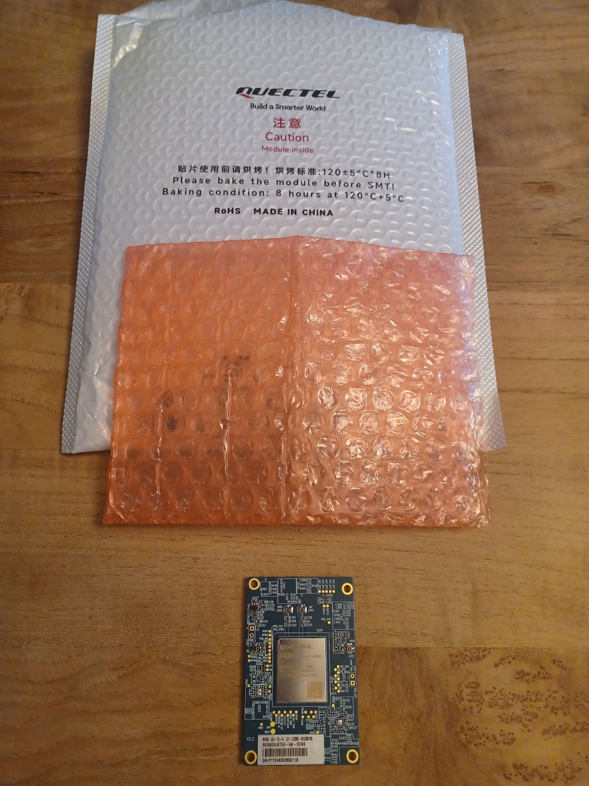
2.2.1 Attach the BG95 to the EVB.
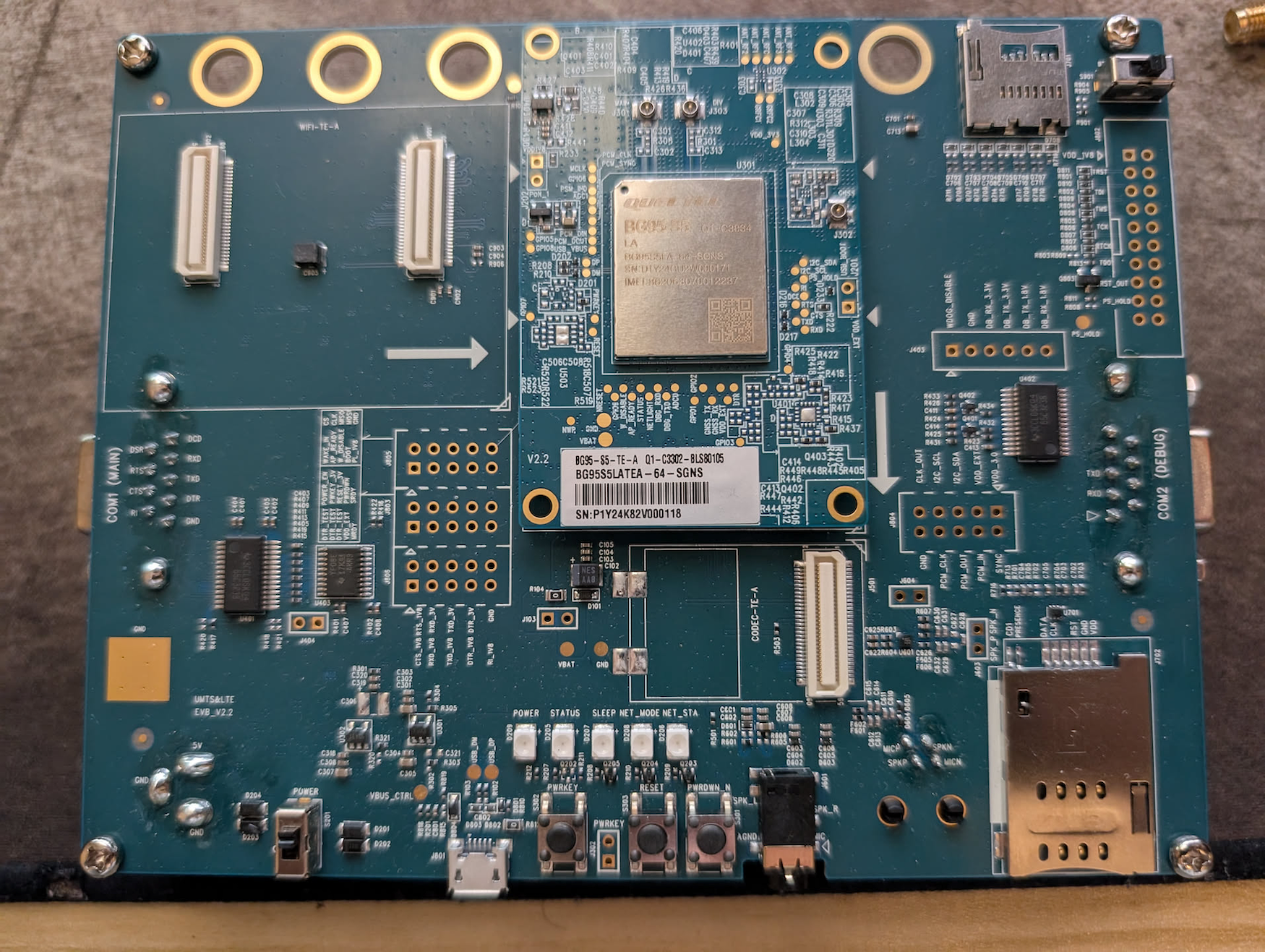
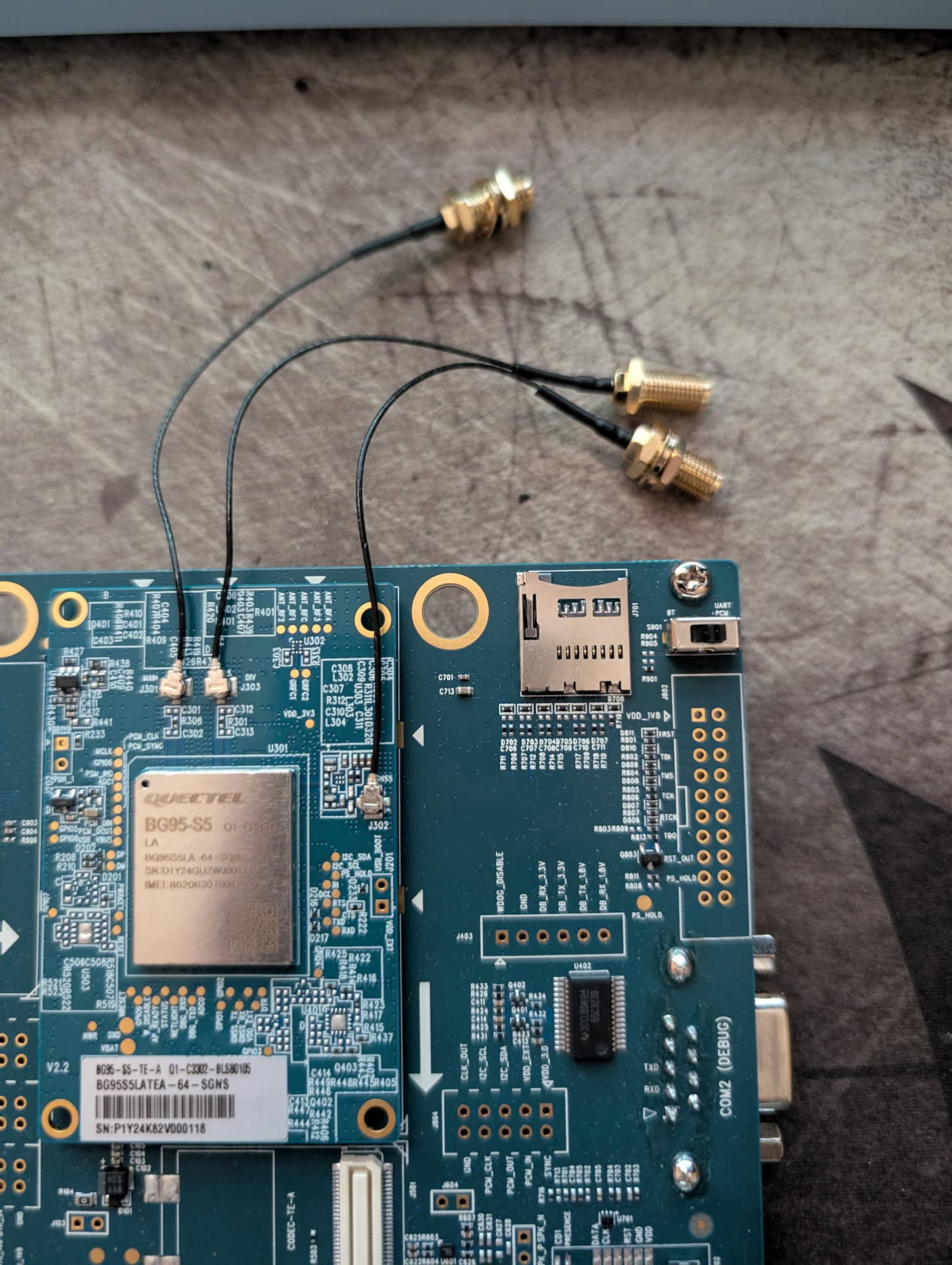
2.2.2 Attach the RF cables to the BG95. They may take a bit of force to attach. The eraser of a #2 pencil may be useful to apply force without damaging the board if you are unable to use your fingers.
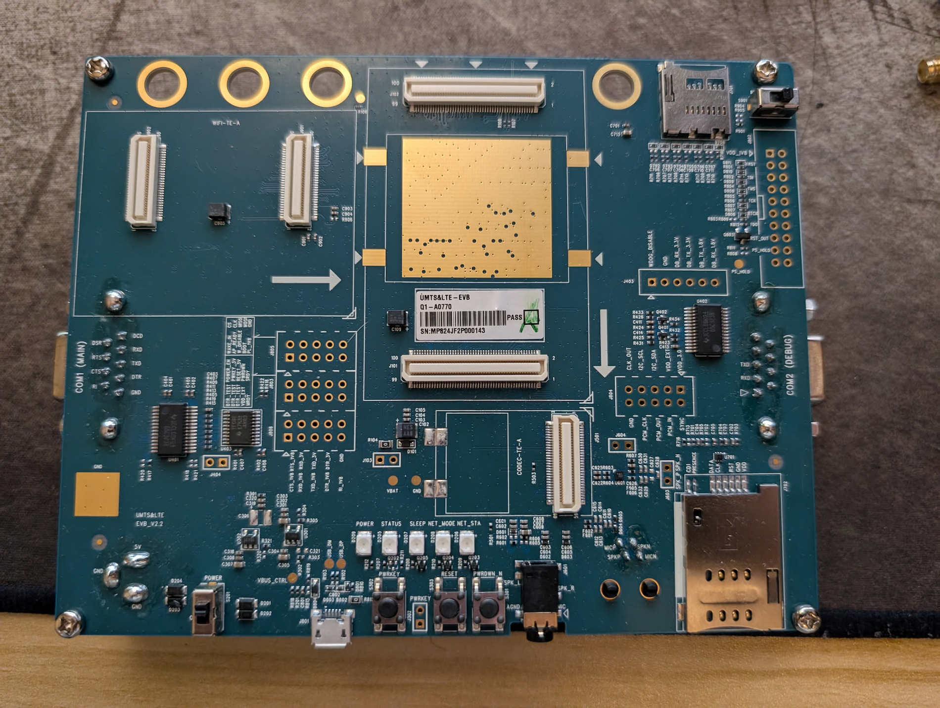
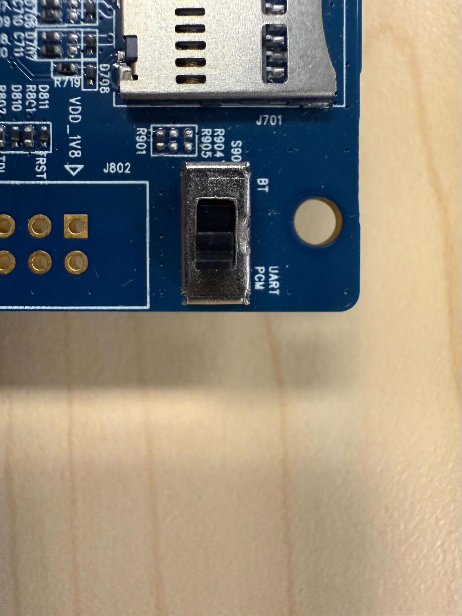
2.2.3 Move the switch in the top right of the board to the “UART PCM Position”. This is done to set the serial interface to the BG95 instead of our empty wifi board.
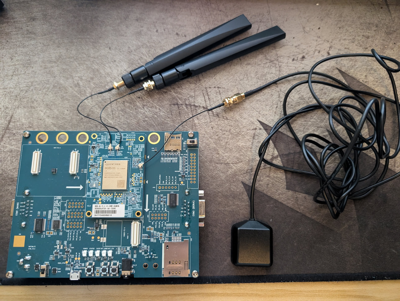
2.2.4 Attach Antennas. The two main antennas attach to the top of the BG95 and the GNSS antenna attaches to the side of the board.
Note, you may only need the earphones if working with voice.
2.3 SIM Card
The UMTS & ELT EVB accepts a standard SIM card (the largest size if your SIM comes in a punchcard).
2.3.1 When inserting your SIM cart into the slot on the board, do so with the pad facing down and the chip on the outer end. You should hear a click once the chip is inserted. If the chip pops back out, then it is not being inserted correctly- try flipping or switching the end. Ensure that the SIM is subscribed to NTN Connectivity.
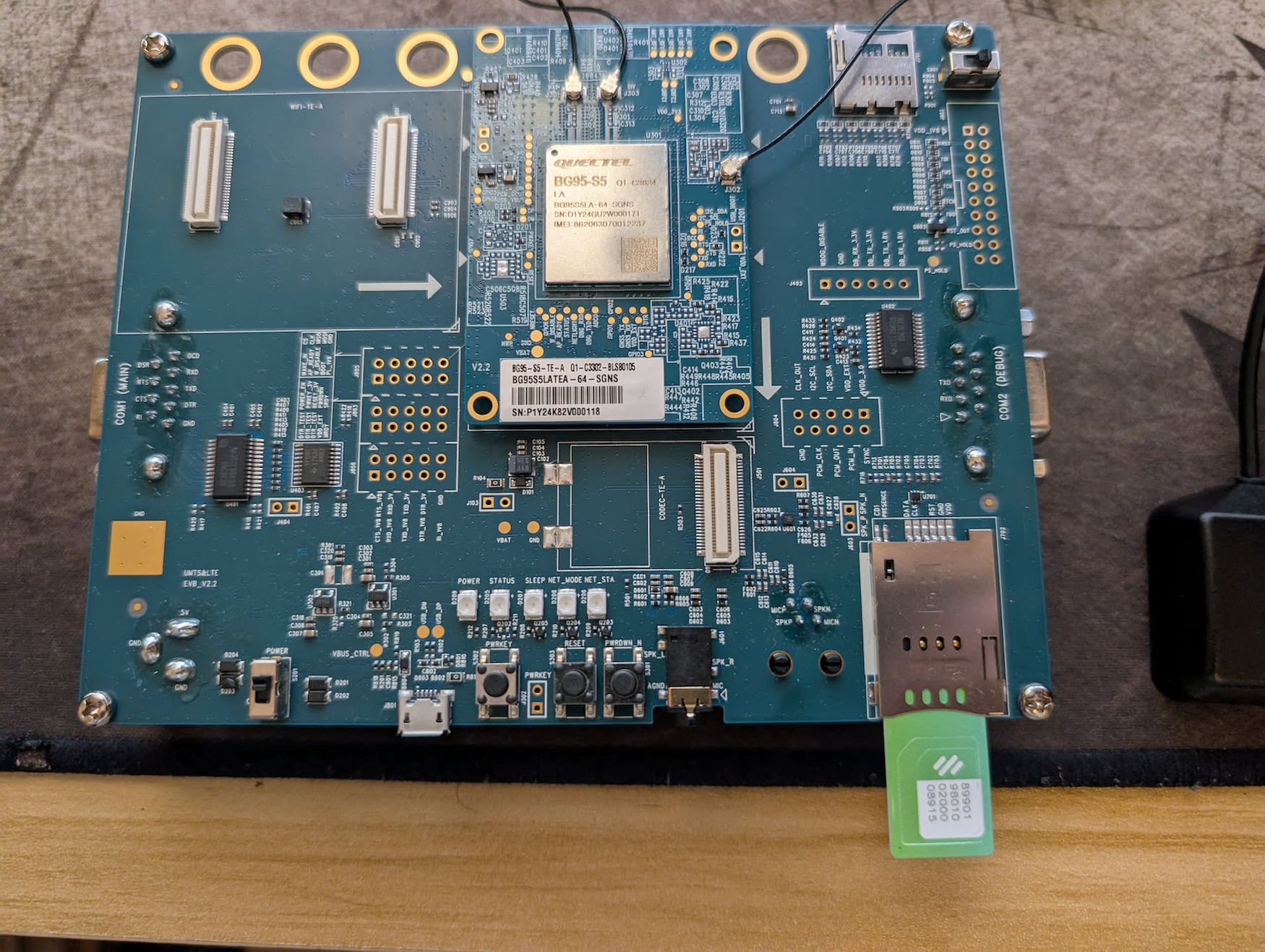
2.3.2 Sim card should be face down.
2.3.3 Insert until you hear a click and the SIM card latches in.
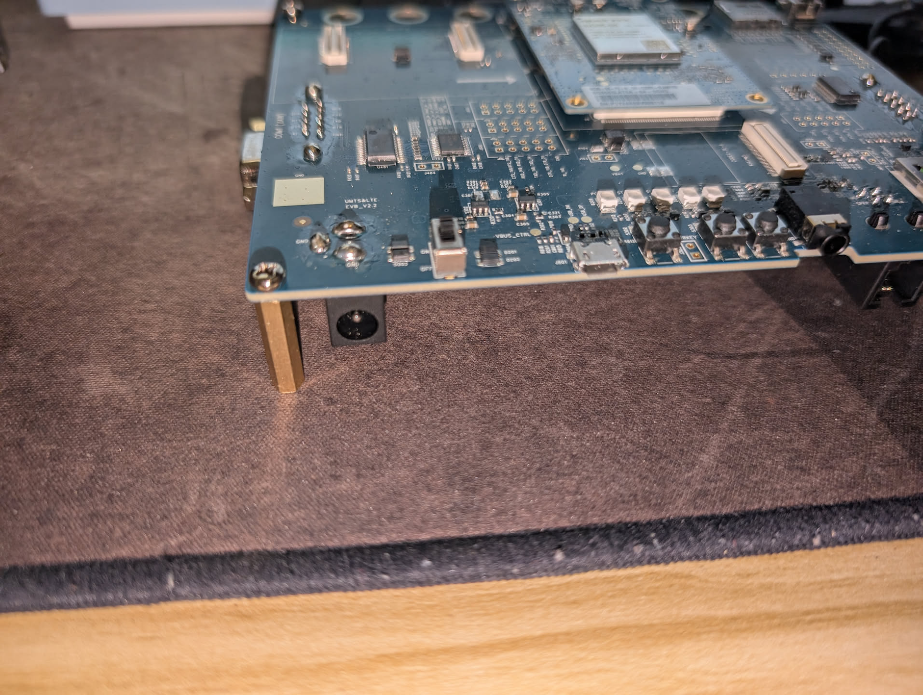
2.4 Power the board
The board can be powered via the included USB cable, or using the 5v barrel plug.
2.4.1 Plug either the USB cable or the 5v barrel plug into your device.
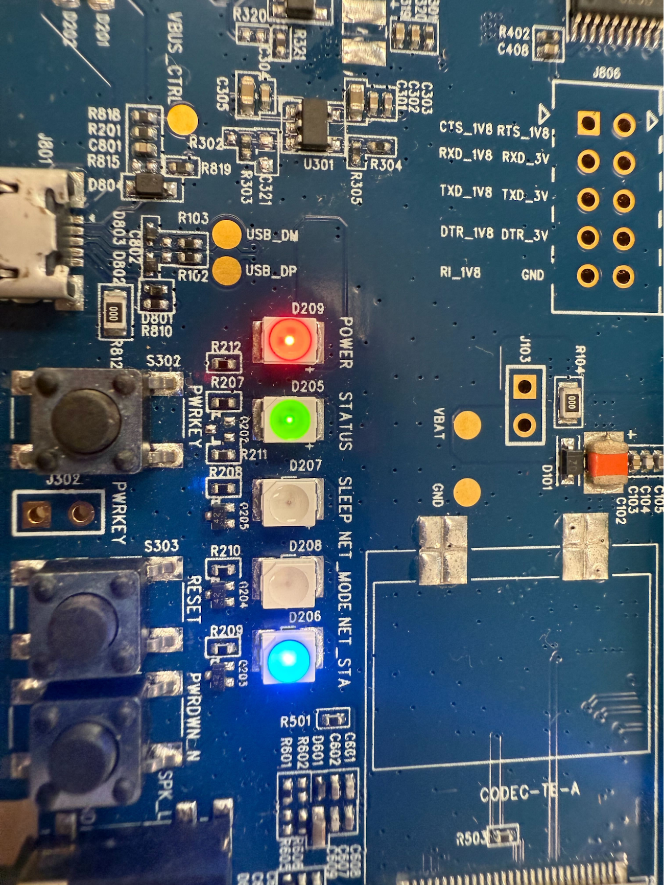
2.5 Power on instructions
2.5.1 Once the device is assembled, to connect power to the board, switch the power switch to ON. The Red LED will illuminate.
2.5.2 To turn on the board, press the leftmost button labeled PWRKEY for at least 1 full second.
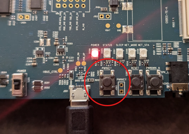
2.5.3 The board should then show a green LED, with another LED blinking blue. The board has been powered on.
3.0 Software Getting Started
3.1 UART Serial communication
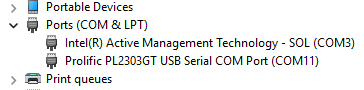
If using the UART Serial Port cable to communicate with the board, no drivers should be needed. You can simply check device manager and find the Prolific Serial Port, and record the port number.
3.2 USB Drivers
Quectel only provides drivers for Linux and Windows, thus the following steps are assuming Windows.
3.2.1 Download drivers from the USB drive included in the EVB box. These drivers are not available online.. The folder should be titled as below.

3.2.3 You may have issues unzipping the entire folder. If you are unable to uncompress the entire file, you should be able to still navigate through the zip file in windows, and extract the below files listed below by dragging or copying them to a new location.
There are various drivers included with the EVB within the drivers folder as pictured below.
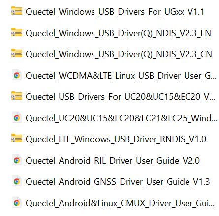
3.2.4 Based on your operating system, select the correct driver to be installed. For this guide, we will install the most recent English version of the Windows driver, “Quectel_Windows_USB_Driver(Q)NDIS_V2.3EN.zip”.
3.2.5 After extracting the zip file containing the driver, simply running “setup.exe” will install the drivers on the system.
3.2.6 Once the driver has been installed, the EVB should be visible to your operating system when connected over USB.
3.2.7 Verify connectivity by opening the integrated windows application Device Manager. Under Modems, we should see “Quectel USB Modem”, and under Ports we should see “Quectel USB DM Port” and “Quectel USB NMEA Port”.
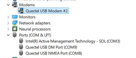
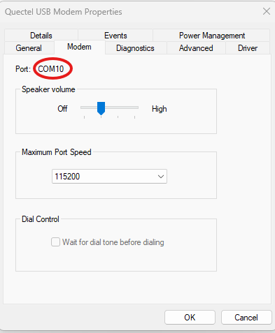
3.2.8 Make note of the COM port Quectel USB Modem is attached to. This can be determined by opening the device within Device Manager and checking the Modem tab.
4.0 Sending AT Commands: PuTTy
This is the easiest way to get connected and the most standard.
4.0.1 Install PuTTy by following the instructions in this link.
4.0.2 Once PuTTy is installed and your board is powered on and connected to your device, launch PuTTy on your device. You will see the following screen for your PuTTy session:

4.0.3 Change connection type to serial, speed to 115200, and Serial Line to whatever the USB modem or serial cable shows up as in the device manager. Clicking enter will prompt the PuTTY terminal to open. If the terminal opens but you cannot type AT commands into it, then you most likely have the wrong COM port entered. Reverify and try again.This behavior may also be due to the board not being on. Ensure that the blue LED is flashing on the board.
5.0 Connecting to Skylo
5.0.1 Ensure that before you attempt to connect, you have a clear view of the sky. Skylo utilizes geo-stationary satellites, and thus ensure that the horizon is clear towards the equator. Avoid indoor areas. Working by a window may work but the best results will be outdoors.
5.0.2 Ensure the SIM card is inserted and the antennas are attached.
5.0.3 First, restore the factory settings of the board and restart to clear any prior configurations.
AT+QPRTPARA=15.0.4 Reset Non Volatile Memory.
AT+QPRTPARA=35.0.5 Restore Factory Settings.
AT+CFUN=1,15.0.6 Reboot board
The following commands will configure the BG95-S5 to be ready to communicate through the satellites!
AT+COPS=05.0.7 AT+COPS=0 sets the board into automatic network selection mode.
AT+QCFG="iotopmode",3
AT+QCFG="nwscanmode",3
5.0.8 AT+QCFG=”iotopmode”,3 sets the board to use NB-IoT instead of CAT M1. NB-IoT is needed to be able to send a signal distinct enough to be detected by the satellites.
5.0.9 AT+QCFG=”nwscanmode”,3 sets the board will only scan for LTE networks. This is important since we are in automatic network detection.
AT+CGDCONT=1,"IP","skylo.ip"5.0.10 Here we are setting the APN (Access Point Name) for the device. Having the correct APN for the network you are trying to connect to is crucial. The above APN is for a Skylo SIM card, so ensure this setting is correct for the Skylo partner you are trying to connect to.
AT+QCFG="band",0xf,0x100002000000000f0e189f,0x10004200000000090e189f,0x1,15.0.11 The above command sets the specific band for the board to use. Here is a breakdown of the command:
0xf is the GSM_bandval. Setting it to 0xf has the board use all supported bands ( EGSM900, DCS1800, GSM850, PCS1900)
0x100002000000000f0e189f is the eMTC_bandval. It is a mask setting the board to the following eMTC LTE bands:
B2, B3, B4, B5, B8, B12, B13, B18, B19, B20, B25, B27, B28, B66, and B73.
The next value is the NB-IoT_bandval. The value is also a mask which sets the board to the same LTE bands.
0x1 tells the board which NTN band to use. This is based on regulatory requirements and changes from region.
- 0x1: 23 For North America
- 0x2: 255 L Band Global
- 0x4: 256 S Band Europe
1 tells the board to apply these settings immediately.
5.0.12 Once these commands are run, the BG95 should have a connection. You can verify this with the following commands:
AT+CSQ5.0.13 This command will return 2 values. The first value is the signal strength indicator. It ranges from 0-31, with a higher value indicating stronger strength. When using NTN connectivity, it is expected to have a signal strength of below 5. If it returns 99, then the board does not have signal. The second value is the bit error rate. 99 means unknown, and is the expected result.
AT+QNWINFO5.0.14 This command returns the access technology, network operator, and band selected. It will return “No service” if there it cannot access a network.
AT+QENG="servingcell"5.0.15 This command will return information about the servicing cell. If there is no signal, it will return “no service”. If it is unable to register with the network, There may be a lot of empty values.
AT+QPING=1,"8.8.8.8",35.0.16 Send out a Ping over the satellite connection and check for response.
5.1 Troubleshooting
5.1.1 Many issues may come down to signal quality. Skylo utilizes geostationary satellites, which orbit above the equator at 35,700 km. Ensure that the board has a clear unobstructed view towards the equator to maximize signal strength.
5.1.2 To test this, try utilizing the GNSS capabilities of the board. This is a good test to see if you can pick up the signals of satellites to begin with. First, enable the GNSS on the board.
AT+QGPS=1
AT+QGPSCFG="gnssconfig",1
AT+QGPSCFG="nmeafmt",1
5.1.3 Next, poll for the location. Note that it can take up to a few minutes to fix a location. If after a few minutes, no location is available, it may indicate that you are in a suboptimal position to receive signals.
AT+QGPSLOC=2
5.1.4 Another issue could be network registration. If AT+QENG is returning empty values, your board could be getting rejected by the network. Ensure you are using the correct APN and your SIM is subscribed to NTN connectivity.
6.0 Using Skylo
Check out these instructions from Skylo partner Monogoto to create a UDP connection: Sending a UDP payload
7.0 Power off the board
To safely shut off the board, send the AT command AT+QPOWD in your terminal. This is the best way to power off the board. Alternatively, press down the PWRKEY button on the board for 1 second. Then switch the power slider to the OFF position. This will manually power off the board.
8.0 Simple Proof of Concept Use Cases
The following are some simple applications that can be created to utilize NTN functionality:
- Always connected GPS tracking
- Log the GPS location of a device no matter where on the earth it is located.
- Always connected sensor monitor
- Record readings from a sensor and upload those values from anywhere on the planet
- Always connected security sensor
- Setup a sensor to detect movement in remote sites or locations
9.0 Helpful Links
- https://docs.monogoto.io/ntn-satellite-networks/ntn-certified-devices/ntn-certified-modules/quectel-bg95-s5-satellite-ntn-network
- https://www.tekmodul.de/wp-content/uploads/2024/04/BG95-S5-Satellite-NTN.pdf
- https://www.quectel.com/download/quectel_bg95bg77bg600l_series_at_commands_manual_v2-0/
- https://www.quectel.com/product/umts-lte-evb-kit/
- https://www.quectel.com/download/quectel_umts-lte_evb_user_guide_v2-1/
- https://www.quectel.com/download/quectel_bg95bg77bg600l_series_qcfg_at_commands_manual_v2-0/
Author:
Eli Bollinger